
What's it all about?
I have always had a fascination for small mechanical things that fly in the air, From the age of about 10 when I first built a rubber powered model aeroplane, then on to control line & now, the present day with sophisticated computer radio control, the hobby still holds my interest.
I ceased flying for 15 years or so, while my daughters grew up, as I felt that the model flying field was a very dangerous place to take them as small children! Now that they are all past that age when they would want to come with me anyway, I thought it was time to take up the hobby again.
I currently have a selection of aircraft, some are shown on this page.
The largest one I have had recently is a "Precedent" Aeronca Champion, has a wingspan of 9 feet with a 20cc four stroke engine pulling it along. This was bought part-finished by a friend of mine for £40.00. He didn't fancy finishing it so I bought it. It flew well enough, although the first flight was a bit hairy owing to the wings not being laterally balanced, a heavy "arrival" & a few repairs later it was as good as new. The undercarriage was originally a weak affair made from too thin piano wire, I remembered that years ago I also had problems with this same type of aeroplane. to remedy this, I fitted a carbon fibre undercarriage - much stronger. This aircraft's stall characteristic was very vicious, because the whole thing was a bit overweight, definitely not for the timid!
All my aircraft are controlled via a "Futaba Field Force 9" transmitter. 1024 PCM type receivers are used which I find very good, easy to program & glitch free. Things have really come on since the early days of radio control! My first radio setup was a "Futaba M series on 27 Mhz.
Nickel Cadmium batteries are amazing now, with much higher capacities available. Nickel Metal Hydride are even better for transmitter/receiver applications, but they are not good for electric flight owing to their inability to give very high amp output. Although capacities are on the way up all the time. Electric powered model aircraft are now quite common, but I still prefer a proper internal combustion engine up front, if nothing else just for the noise & smell!

I taught myself to fly years ago, by throwing various models in the air & picking up the bits until I got the hang of it. Thankfully this didn't take very long - about 5 or 6 (old & cheap) model's worth! After a while I got quite good at it, I even won a club competition or two!
There is something good about remote control, especially the three dimensional aspect of aircraft. I would not recommend anyone to teach themselves these days, insurance needs to be your first consideration. I am currently once again, a member of "Dewsbury Model Aero Club" & the B.M.F.A (British Model Flying Association) With this membership comes 3rd party accident insurance at a low premium, very important in case you crash into a person or a building. A modern model aircraft is a very powerful dangerous un-guided missile in the wrong hands! In flight mechanical failure can never be ruled out either.
Unlike years ago, when I would stand on the field flying my plane, using at least a gallon of fuel per afternoon! totally impervious to the cold & bad weather, I prefer fair weather flying these days!

Experiments with model aero engines
I enjoy fiddling about with mechanical objects generally, so model aero engines are a prime target for me, old two strokes don't cost that much, if you mess up! so here are a few of my observations.
I obtained a worn out OSFX46 from a friend for the princely sum of a network card for his PC! this engine was a bit past its sell by date to say the least, the cylinder head was damaged & the piston & liner were positively corrugated! I looked on the excellent "Just Engines" website & they advertise a "OSFX46 short engine".
The price is reasonable enough at approx £45.00 (inc postage) so I sent off for one, nothing to lose but £45.00 methinks. I may be wrong here, but what I received appeared to be a "Super Custom46" with the "SC" name milled off the crankcase. I fitted my OS carburettor & backplate from the OSFX46 & bolted the engine into a "Weston Cougar" funflyer to have a play with it. I then sent off to "Just Engines" for a "Genesis" throttle pipe. This duly arrived the next day & I bolted that to the engine, using 5 minute epoxy as a sealant on the exhaust port. The engine was very tight over TDC, which is good on an "ABC" (Aluminium piston with Brass Chomed liner) two stoke engine. Using my own fuel mix (see below) The engine started well & I ran it in using the usual technique for "ABC" engines, that is, get the engine's piston & liner up to temperature quickly, so I didn't run it very rich etc, in fact I "thrashed" it a bit if I am honest! After a couple of tankfuls of fuel the engine ran very smoothly - I adjusted the "bottom end" mixture needle, & after 4 tankfuls through it, I clocked 12,000 RPM on a 12 x 5 prop - very good - only just 82 Db I think though! 12,000 RPM is a little more than my usual engine propeller configuration allows, owing to the 82 Db noise regulations at our club flying site.
Anyway, I took the model down to our flying field & the performance was amazing in the "Cougar", which had previously been fitted with a very good "Irvine40 " with standard silencer. But now ..... Take off in 4 -5 feet, straight up - vertical - as fast as most models fly level! prop hanging on quarter throttle, great idling reliability - Impressed!
At this point I must mention that I modify my fuel:
I always buy a normal gallon of "Superglo" or similar with 5 % nitromethane , I divide this into 3 equal parts in other 1 gallon fuel containers, then top up the containers with neat methanol, shaking well, so I have 2 thirds neat methanol, one third standard fuel in each gallon container. I run all my engines (mainly Lasers & a couple of OS) on this mixture with absolutely no ill effects. The "bottom end" of the carburettors on my engines need leaning out a bit, as does the main needle.
The benefits are:
Much less oil residue on my models, smoother running, more reliable engines, better fuel economy - need I say more? The "purists" may moan about this, but it works for me. Years ago, with my "Webra Speed60" & "Speed40" size two strokes doing 15,000 + RPM (in a less noise conscious world), I always used standard fuel. But even in the early 1980's I used to run my OSFS60 & OSFS40 (four strokes) on this "diluted" fuel mix with no ill effects at all!
Back to the engine:
One thing bothered me - the milled off "SC" casting on the crankcase looked tacky, plus I got fed up of explaining to people who asked "what's that engine?" So as soon as I got chance, I dismantled the engine to have a look at its internal components & quality, & see about transferring the internal components & cylinder head into my OSFX46 crankcase.
A COMPARISON:
CRANKCASE & CYLINDER HEAD: near enough same visible quality to the OSFX46
PISTON & LINER: slightly different, shinier, & well made
CRANKSHAFT: not so good - inlet port physically smaller, crankpin drilling too long, location hole being drilled through into the ball race location area, not a problem though. According to my digital micrometer, the crankpin was machined smaller in diameter than the crankpin on the old OSFX46, & the new con rod is a better fit on the old OS crankpin - not tight - just right.
BEARINGS: I didn't like these much, the front bearing was thicker than the OS, but the rear main bearing had a very thin plastic ball retaining collar which I personally did not like, I felt that this was not sufficient to hold the balls in position seurely over a long period . I removed it, played with it, and destroyed it very easily!
SOLUTION:
I bought a new rear main bearing from a local supplier "Spen Bearings" - Japanese manufacture, high quality & it only cost me £3.00!
I thoroughy cleaned, lubricated & re-assembled the OSFX46 using the piston, conrod, liner, cylinder head & nice shiny prop driver from the "Just Engines" short engine.
RESULT:
I NOW HAVE AN ENGINE WHICH HAS "OSFX" CAST ON THE SIDE OF THE CRANKCASE & SEEMS TO RUN JUST AS WELL AS THE "SHORT ENGINE" DID.
No criticism at all is levelled at "Just Engines" I received what I expected to receive - a "clone" engine at "clone" prices & besides, it ran very well indeed. Their mail order service is very efficient as well.
Who knows I might even rebuild the other engine too!
- I wonder what the new OS AX range are like?
Messing about with the valve settings on an old OS FS60 four stroke engine
I recently restored an old OS FS60 engine, the type with the machined aluminium carburettor & open valve rockers. this was bought from a friend for £60.00. It had been in a box of junk for 20 years & was so gummed up, it would not turn over at all. I carefully dismantled it & dropped all the components into a pan of neat methanol for a couple of days, agitating the methanol frequently & changing the resulting contaminated mixture 3 times for new methanol. The amount of sludge that came out of the engine was surprising. After using an old toothbrush dipped in the methanol, I ended up with a clean engine - inside & out. Warning: If you do this, wear gloves when handling methanol - I didn't & temporarily desiccated my hands, which is not a good idea! I dried off, polished up the cylinder head, lubricated & re-assembled the engine. The bearings were in remarkably good order, plenty of compression as well. It started easily & runs very well & is reliable at idle for long periods. It was fitted in a "Majestic Major" which is a vintage style plane, ideal for flying on pleasant summer afternoons at the "Brighouse Vintage Club" flying site at Stainland. The engine's performance was not up to modern OS fourstrokes.
I had an idea:
As the fuel air mixture goes into the cylinder, past the inlet valve stem, this mixture is very cold, causing the inlet valve stem to contract.
With the exhaust valve, the opposite happens - the products of combustion leaving the cylinder are very hot - causing the exhaust valve to expand.
I decided to set the valve clearance on the inlet valve to zero clearance. I did this with the engine cold.
so ....... no clearance at all on the inlet valve rocker, normal clearance on the exhaust valve rocker.
Result:
Same fuel, same prop, same day = 1000 RPM more than with the normal valve rocker clearance! I can go into a coma much quicker now, while flying my "Majestic Major" ! It flies itself really, all I do is occasionally steer it about & eventually land using much "down elevator". Stress free flying when I have had a busy week at work!
This setup just opens the inlet valve fractionally earlier than normal & closes it fractionally later than normal.
A bit more fuel/air mixture in the cylinder gives a bit more power. I feel that this may only be effective on early fourstrokes, As I am sure that the manufacturers have since altered the cam profiles to give this valve "lap & lead" effect - a bit like on a steam engine maybe. Having said that, I haven't tried it on any other fourstrokes.
What's next? "variable valve timing"?
HOW TO SET UP A MODEL ENGINE CARBURETTOR (so that the engine runs properly!)
There is definitely no witchcraft involved in this, all that is required is a good bit of patience, plus the knowledge of what to do & why you are doing it. Take your time & you will usually get it right the first time!
Over the years I have seen quite a few models hitting the ground - or worse! just because the engine was not set up correctly in the first place & stopped suddenly. At your flying field, you will observe that some flyers just start their engines & fly their models successfully, seldom having to shout "dead stick" or plummetting into the ground, but some other modellers seem to constantly mess about with their engines on a weekly basis. Crashing into trees & stone walls is a slight problem if your engine has stopped & the obstacle is in your flightpath!
Manufacturers often leave the "idle needle" in approximately the right place, but it is dependent on other factors such as engine position in the airframe, fuel type etc. In my experience, usually the high quality end of the engine market come out of the box better setup, but not always. One well known quality British manufacturer actually runs each engine before it is dispatched, & these are ready to go, only a fractional movement, if any, is needed to compensate for the above conditions.
Also you will need at least a reasonable quality engine in the first place, preferably with some sort of compression, and without air leaks around the base of the carburretor inlet or needle valves!
Before I start describing the process of "setting up the carb", I need to mention the pros & cons of "exhaust pressure feed". The idea is that a pressure tapping is taken from the silencer via a small nipple & connected by a pipe to the fuel tank. The other vent pipe is blocked with a plug after filling. The exhaust back pressure slightly pressurises the tank, forcing fuel to the carburettor. The problem is that the main needle setting can become more critical, & throttle pickup can become erratic as the pressure from the silencer is much lower during idle. If the pressure pipe should fall off, or the silencer come loose, then the engine becomes too lean & stops running! Some people moan about potential contamination of the fuel with exhaust by-products, but in reality I think that's maybe taking it a bit far. Although you can often see a little carbon & burnt oil in the silencer pressure pipe & in the inside wall of the fuel tank.
I prefer silencer pressure for these reasons:
1) constant head of fuel at the carburettor inlet
2) fuel doesn't run out of the vent pies when the aircraft is inverted (in flight or otherwise), or when carrying it nose down back from the flight line
3) Fuel doesn't run everywhere in the car when you forget to drain the tank when going home after a day's flying
4) Depending on the physical position of the carburettor on some engine types, it is sometimes difficult to get the tank in the right position to ensure a good feed to the carburettor in all flight attitudes without a pressure feed. If you can build from a kit, then it is usually possible to arrange the tank placement to suit the engine, but on the A.R.T.F. type, not all engines have the carburettor on the centre line of the model. If your engine has the carburettor lower than the centre line of the tank, then the fuel siphons out of the tank to the carburettor & drips onto the ground, although at least the engine always has a "head of fuel" when it is the right way up! You then run the risk of a temporary drop in power or complete engine stop, owing to fuel starvation when flying inverted or during a rolling maneuvre. There are specialised pumps available for model engines, but I have never had the need to use them. My models fly well enough for my non-competitive sport flying aspect of this hobby.
Non-pressure is usually fine for "vintage" type models which just stooge around slowly, mainly in an upright position, but I have personally found that a well known, very small capacity .30 size four stroke engine from a Chinese manufacturer, seems to run better with pressure, & develops a little more power.
I have also seen a very large number of "dead stick" landings from these non-pressure fed "vintage models" with all sorts of engine types & sizes fitted, the engine having stopped suddenly, shortly followed by gliding into walls, trees, fences & other various obstacles - generally culminating in heavy arrivals into the ground with considerable damage to the airframe in the process!
I have always used "inline" fuel filters on all of my engines, as a very small piece of grass or grit can easily block the passage of fuel past the extremely fine main needle valve. If this happens during take off, or climbing out after a slow low pass, then the whole model, radio & engine are at risk.
Please note: With these filters, always check that the are screwed together tightly before use, so as not to let any air in, around the "O" ring seal.
There are a few different styles of carburettor fitted to model glowplug engines, but the operation of the most common type is described below:
First, have a good look at the carburettor's construction & notice that it usually consists of a rotating barrel with a large hole through at 90 degrees to the barrel, with a master needle valve at one side & a second needle at the other side, which is often in the form of a small slotted screw in the end of the barrel.
As this barrel is rotated by the throttle servo it does two things:
1) it allows more or less air into the engine - and at the same time .........
2) it allows more or less fuel into the engine via the position of the barrel relative to the adjustable "bottom end" needle valve.
More fuel & air in the correct ratio equals more RPM.
Less fuel & air in the correct ratio equals less RPM
The main needle valve is usually a long, thin pointed needle, allowing very fine adjustments. The idle needle is shorter & blunter, therefore allowing a much quicker change of fuel admission from the spraybar as the throttle barrel is rotated into the open position.
Some engines use the "air bleed idle system" but as far as the setup is concerned, it is worth noting that the "air bleed screw" which is usually at the side of the carburettor (not to be confused with the "throttle stop screw") which is usually on the top of the carburettor, must be adjusted in the opposite way to the "internal barrel" type ie: to lean out the idle = unscrew, to richen the idle = screw in
The following description assumes the spraybar idle needle type:
As the barrel rotates, the spraybar (the thin tube in the centre of the barrel, where the fuel comes out of) moves further away from the idle needle which is positioned centrally to the spraybar, the more it is opened, the further away the spraybar moves away from the idle needle, letting more fuel into the engine's intake. The main needle is in a fixed position always, initially set by the operator, so with the engine on full - (carburettor wide open), the needle is first manually adjusted to let the correct amount of fuel into the spraybar, this is sucked into the engine on each induction stroke in the form of a spray, a bit like a paint spraygun.
So .......... Start the engine with the throttle initially set low, run it up to full power, adjust the top end (master) needle valve until the engine "peaks" out - hold the model nose up to check that you are not running too lean. place the model back on the ground & slowly close the throttle until your engine idles. Set the throttle travel by either adjusting the servo's travel manually or use "ATV" (servo travel end point adjustment) on your radio transmitter, until the engine runs at an acceptable idle speed.
The following adjustments should not be carried out until the engine is correctly run in, as a "tight"engine may be reluctant to run slowly at first.
Once the engine is idling, open the throttle quickly & observe what it does, if it splutters its way up to full power, then the idle needle is too far out - too rich. If the engine "coughs" & sounds like it is going to cut out, or actually stops, then the idle needle is set too far in - too lean.
With a small screwdriver (I have a really long thin screwdriver for this bit, so that I can set the idle needle position while the engine is running, without getting my fingers in the spinning prop arc - ouch! - that brings back memories of my youth, I still have the scars to prove it!) turn the idle needle in or out depending on whether the engine's mixture is lean or rich. Only move about a sixteenth of an inch (or approx 1 millimetre) at a time in or out, then open up the throttle again to see what happens. the ideal situation is when the engine picks up quickly without hesitation. The main needle now needs adjusting slightly, owing to the change of position, inside the end of the spraybar, of the idle needle valve. Some engines are very critical of the mixture settings, others are not.
Run the engine on full, re-adjust the main needle, hold the model verically again to verify that you are not going too lean, which you do not want as the aircraft climbs out on take off, then place the model down on the ground again & check for pickup from idle to full power. Each time that you change the position of the idle needle valve, re-check the position of the main needle valve. As you reach the optimum "bottom end" setting, the engine may be idling too fast, so subsequent re-adjustment of the "ATV" (or servo travel end point adjustment) may need to be carried out once again.
Do not, under any circumstances rush this procedure, because if you get it wrong, then you run the risk of a "dead stick" at the wrong time!
Don't forget, whenever you adjust the "Bottom End Needle Valve", always re-check the setting of the "Top End Needle Valve" .................................
The engine's mixture settings are very much affected by the fuel type, my "more methanol - less oil mix" needs the settings all to be leaner, as in each induction stroke, the ratio of methanol to oil is a good bit more than normal, so there is more combustable mixture in each cylinder full - if you see what I mean! If you change fuel type, always test your throttle settings before flying the model.
Under normal circumstances though, variations in external air temperature, air pressure & moisture density ie: running in Summer & Winter on hot or cold days usually only requires a small adjustment of the main needle valve, if any.
All the above information is not copied from any manuals, it is based on my own experience of running model aero engines over the years with very few fuel/mixture problems.
If you disagree with the above brief description on "How to setup a model engine carburettor", Please do not email me, because you could always of course use the cast iron cauldron based method - with "wing of bat, eye of newt"etc etc !
Making your own replacement Piston Rings for model aero engines
I made a new piston ring for an old LASER engine owned by a friend.
The previous owner had broken a quarter of an inch section off the original ring, the engine still ran, but not very well & parts were unavailble for it as it is a very old engine! I am not a trained engineer so apologies in advance to the purists!
Here's how I did it:
Remove the cylinder head assembly, so as to get to the piston & liner.
using vernier calipers, carefully measure the depth of the groove on the piston (remove the broken ring first)
using the same vernier calipers measure the internal bore of the liner.
Obtain a piece of high quality cast iron, hold in a 3 jaw chuck on a lathe, even a vert small one will do!.
Depending on your equipment, machine the cast iron slowly - without proper carbide tipped cutting tools, if you go too fast you will soon blunt high speed steel & the tool will need regrinding frequently. Just go easy on the iron, later on you will smash it to bits if you are too heavy handed!
Centre drill the cast iron bar, slowly drill in a couple of inches or so, open out & finish bore the internal diameter to almost match the piston's groove diameter - bore it slightly bigger by to allow for the closure of the gap in the ring later.
Turn the outer diameter to approximately 50 thou above the diameter of the bore of the cylinder liner.
You should now have a cast iron tube about an 2 inches long.
Part this off & remove the rest of the cast iron bar stock from the chuck.
Using a very fine slitting saw, carefully cut a slit all the way down one side of the tube - do not clamp the tube in a vice!.
Clean up the slit gap with some "wet or dry" sandpaper or fine emery cloth.
Next, Put a piece of mild steel bar in the 3 jaw chuck & turn it down a "couple of thou" larger that the piston's groove depth for a couple of inches.
Slide your cast iron tube over this mandrel & clam it tightly to the mandrel with a couple of "jubilee" clips.
Make sure that the slit in the side is firmly closed by the pressure of the "jubilee" clips.
Finish machine the outside diameter of the ring to match the liner's bore
Very carefully, part off the ring to match the groove in the piston, err on the "very slightly too thick" side!
DO NOT remove the mandrel from the chuck at this stage
You now nearly have a piston ring, but not yet!
Using a "whetstone" or wet or dry sandpaper with a little oil on it, clean up both sides of the ring to a good finish.
Test the gap in the piston s you go, but you do not need to fit the ring, just slide it into the groove to see how it's doing.
When you are happy with the fit, (it must not be too tight) very carefully fit the ring to the piston after first removing all traces of gritty oil from the sandpaper process.
Be careful here, the ring will allow expansion just enough to get it over the crown of the piston. If you break it, play J.S. Bach's "Air on a G string", smoke a cigar, & repeat the above process. This is why I recommended to machine a 2 inch length of piston ring material & not to remove the mandrel from the chuck. Once the mandrel leaves the chuck it is time consuming to get it to run accurately. If you have a Collett system it's better!
Once you successfully fit the new ring, re-assemble the enging using copious amounts of oil.
When first running the engine, treat it as you would a new one, it needs a little running in.
There you have it then, a new piston ring & an engine that works again. The old Laser 75 runs as it should do now.
SOME OF MY CURRENT MODEL AIRCRAFT
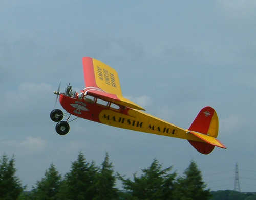
Very easy & relaxing to fly, but you are in danger of losing the will to live & slipping into a coma when flying it!
Powered by a very old OS FS60 soon to get a Laser fitted!
FROM THE SUBLIME TO THE RIDICULOUS!
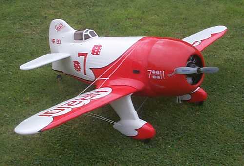
One of my favourite aircraft is the GEEBEE, this is a 71 inch span A.R.T.F. model from the YT International range.
Powered by a new LASER 150
It flies very well, but landings can be a problem!
I slightly damaged the wheel spats on the first landing, but I hope to get it right next time!
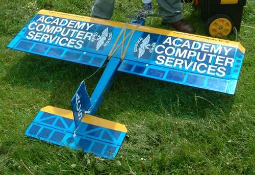
This is a LIMBO DANCER aerobatic funfly aircraft, it really is very good to fly - sometimes seems to defy gravity!.
It was a bit underpowered with only a .30 fourstroke engine, but I then fitted a Laser 70 & the performance was stunning!
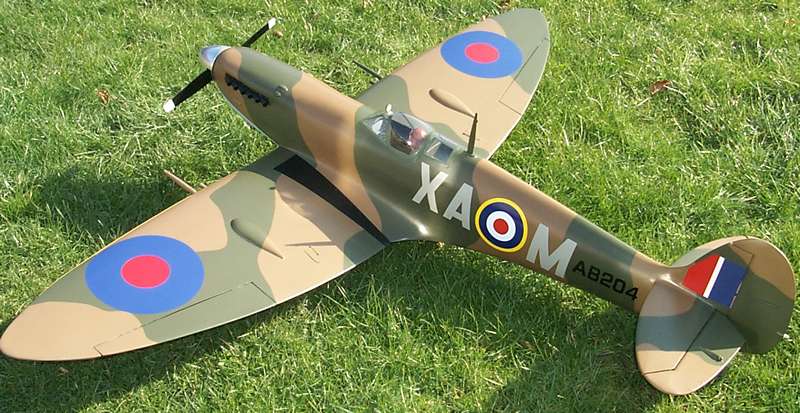
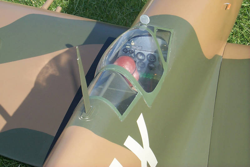
I have just finished this exact 1/6th scale "Mick Reeves" Spitfire
I didn't go over the top on scale detail, but just wanted a model spitfire that actually looked like one!
I especially like the little spring-loaded doors in the wing where the flap actuator arms pop up when the flaps are down, like on the full size.
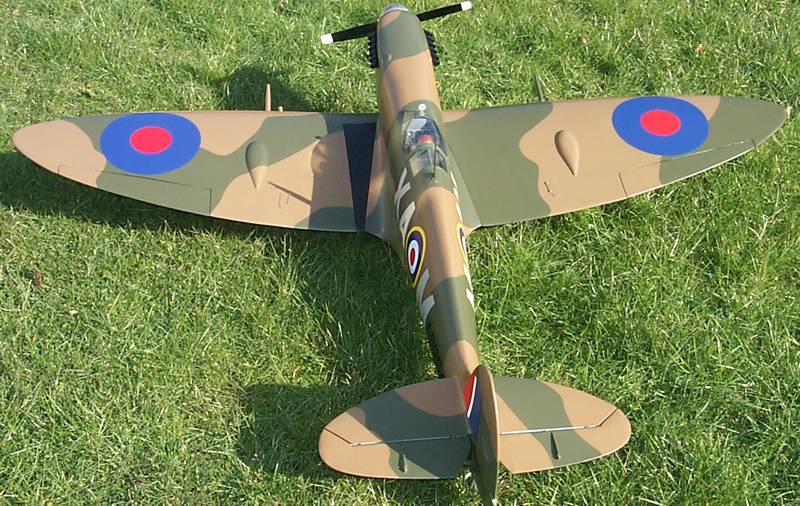
Epoxy-Glass fuselage & built up & sheeted wings etc.
It has a set of Mick Reeves all metal retracts & oleo legs with a seperate high torque, metal geared servo for each leg.
It is fitted with a Laser 150 engine
As soon as the weather gets better, I will enjoy flying this one - it really looks the part!
LASER ENGINES
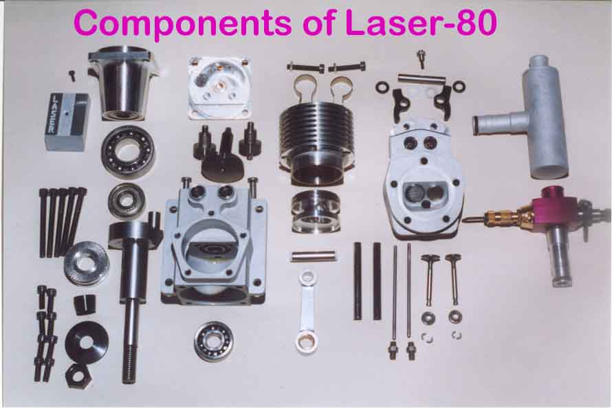
After buying a couple of secondhand LASER engines from a friend recently, I now find it impossible to use any others - although I do have a really old OS FS60 (with the exposed rockers & valves) which I like just because of what it is. I have since bought some more new LASER engines, and it is of my opinion that they are easily the very best available model aircraft engines for several reasons: They work!,They are manufactured in England, They are incredibly good quality Engines,They are completely machined from solid metal, not "Monkey Metal" castings like some other model engines. All the fragile parts, like pushrods & camshafts are at the back of the engine, out of the way if you crash! They are very powerful, loads of torque for swinging bigger props, with a nice deep exhaust note to boot! They run on almost any kind of fuel, They are absolutely the most reliable engines I have ever used, & you can leave them idling on the ground, (even when mounted inverted) for as long as you have fuel in the tank, go away & have a cup of tea, then as soon as you throttle up, the throttle response is instant & very "snappy" - No worries on low tickover flypasts, these LASER engines alway pick up! I have a couple of LASER V twins - these engines are really good. One of them is about 15 years old, bought from Phillip Kent & runs just as well as the new one. This old LASER 180V is in a 1/4 scale clipped wing Piper Cub, The new LASER 200V is in a Flair Hannibal, both models fly & sound really well. You cannot buy them in the model shops, all you do is email or phone in your order & card details, then the engine arrives with you a day or so later. The prices are comparable, if not a little less than other model engine manufacturers. The person you speak to on the phone when ordering your engine or making an initial enquiry is Neil Tidey, he is the man who designed & developed the engines in the first place. All is explained in great detail on his website.
Disclaimer:
I have no connection with LASER engines, only as a very satisfied customer Look at the quality of the component parts in the picture below
Don't just take my word for it, click above & visit the LASER website
Do yourself a favour - buy one!
Another good site to visit if you haven't already been there is YT International.
The models that they distribute are of very high quality
The GEEBEE above is one of their A.R.T.F'S
(Click the logo below to visit the site)